
Showing posts with label clean tech. Show all posts
Showing posts with label clean tech. Show all posts
Wednesday, February 27, 2013
Wednesday, February 20, 2013
Fracking Fluids #1

Frack Fluid, Briefly
Hydraulic fracturing uses large volumes of extremely high pressure fluid injected deep below the ground to create fractures in the oil- or gas-bearing rock formation. These fractures are kept (propped) open with a “proppant” (or “propping agent”) - often a silica sand - allowing the hydrocarbons to flow from the formation to the well-bore. There have been many innovations in hydraulic fracturing. These past posts spot light several inventions and the patents that support them..
The fracking fluid contains major groups of chemicals that serve specific functions needed to achieve successful and efficient recovery of the underground hydrocarbons. A gelling agent or hydration aid reduces friction of the overall mixture with the well-site piping and well-bore by modifying the viscosity of the fluid. Biocides are used to control bacteria growth, thereby maintaining the integrity of the fluid, and the health of the formation. A crosslinker increases the viscoelasticity of the fracturing fluid, thereby improving proppant transport and distribution within the fractures created in the formation. Crosslinkers create a chemical bond link between the polymer chains used in the gel. Breakers work in opposition to crosslinkers - they reduce viscoelasticity and viscosity by breaking the polymer chain links and are used in cleanup of the fracture system. Surfactants (think soap or detergent) enhance recovery of the hydrocarbons by reducing their surface tension with the formation rock.
(A more user friendly version of the fracking fluids tables below are available at Way Better Patents.)
The US Department of Energy reported several years ago that a typical fracking fluid is composed by volume of:
| Constituent | Percent by volume |
|---|---|
| Water & sand | 99.51% |
| Acid | 0.123% |
| Friction reducer | 0.088% |
| Surfactant | 0.085% |
| Potassium chloride | 0.06% |
| Gelling agent | 0.056% |
| Scale inhibitor | 0.043% |
| pH adjusting agent | 0.011% |
| Breaker | 0.01% |
| Crosslinker | 0.007% |
| Iron control | 0.004% |
| Corrosion inhibitor | 0.002% |
| Biocide | 0.001% |
The exact blend of a frack fluid varies based on well-specific conditions, source water characteristics, and the vendor product used, and the individual treatments will use from 3–12 of the additives besides water and the propping agent. The purpose of the individual components is listed in the following table here.
| Additive type | Common Compound(s) | Purpose | Common Use |
|---|---|---|---|
| Diluted Acid (15%) | Hydrochloric acid or muriatic acid | Help dissolve minerals and initiate cracks in the rock | Swimming pool chemical and cleaner |
| Biocide | Glutaraldehyde | Eliminates bacteria in the water that produce corrosive byproducts | Disinfectant; sterilize medical and dental equipment |
| Breaker | Ammonium persulfate | Allows a delayed break down of the gel polymer chains | Bleaching agent in detergent and hair cosmetics, manufacture of household plastics |
| Corrosion Inhibitor | N,n-dimethyl formamide | Prevents the corrosion of the pipe | Used in pharmaceuticals, acrylic fibers, plastics |
| Crosslinker | Borate salts | Maintains fluid viscosity as temperature increases | Laundry detergents, hand soaps, and cosmetics |
| Friction Reducer | Polyacrylamide; Mineral oil | Minimizes friction between the fluid and the pipe | Water treatment, soil conditioner; Make-up remover, laxatives, and candy |
| Gel | Guar gum or hydroxyethyl cellulose | Thickens the water in order to suspend the sand | Cosmetics, toothpaste, sauces, baked goods, ice cream |
| Iron Control | Citric acid | Prevents precipitation of metal oxides | Food additive, flavoring in food and beverages; Lemon Juice ~7% Citric Acid |
| KCl | Potassium chloride | Creates a brine carrier fluid | Low sodium table salt substitute |
| Oxygen Scavenger | Ammonium bisulfite | Removes oxygen from the water to protect the pipe from corrosion | Cosmetics, food and beverage processing, water treatment |
| pH Adjusting Agent | Sodium or potassium carbonate | Maintains the effectiveness of other components, such as crosslinkers | Washing soda, detergents, soap, water softener, glass and ceramics |
| Proppant | Silica, quartz sand | Allows the fractures to remain open so the gas can escape | Drinking water filtration, play sand, concrete, brick mortar |
| Scale Inhibitor | Ethylene glycol | Prevents scale deposits in the pipe | Automotive antifreeze, household cleansers, and de-icing agent |
| Surfactant | Isopropanol | Used to increase the viscosity of the fracture fluid | Glass cleaner, antiperspirant, and hair color |
Source: Modern Shale Gas Development in the United States: A Primer. USDOE, NETL. 2009.
How do the ingredients of Halliburton’s CleanStim fracking fluid compare to the generic list above?
| CleanStim Constituent | Common Uses |
|---|---|
| Enzyme | Soybean Paste, Fruit Juices and Nectars, Laundry Detergent, Dishwasher Detergent, Toilet Cleaner, Industrial Pulp and Paper Processing Aid |
| Ethoxylated Sugar-Based Fatty Acid Ester | Synthetic Food Flavoring Substance, Natural Baby Wipes, Baby Wash and Shampoo |
| Inorganic Acid | Cheese, Alcoholic Beverages, Wheel Cleaner, Rust Dissolver, Dishwashing Detergent |
| Inorganic Salt | Food Starch – Modified, Water Clarifier, Fish Tank Water Treatment |
| Maltodextrin | Sweetener, Glaze and Icing Sugar, Coconut Milk and Coconut Cream, Shower Gel |
| Organic Acid | Fruit Juice, Dishwasher Cleaner, All-Purpose Cleaner, Hand Soap |
| Organic Ester | Liquid Egg Products, Food Resinous and Polymeric Coatings, Hairspray |
| Partially Hydrogenated Vegetable Oil | Confectionary Chocolate Coating, Hair Detangler, Body Lotion, Lip Liner, Soap, Lotion, Cream and Other Skin Care Formulations |
| Polysaccharide Polymer | Canned Fish, Processed Cheese, Dairy-Based Desserts and Drinks, Beer, Toothpaste |
| Sulfonated Alcohol | Egg White Solids, Marshmallows, Dishwashing Liquid, Home Dilutable Cleaner, Shampoo, Acne Scrub, Shaving Cream, Liquid Hand Soap |
In part 2 we’ll look at some fracking fluid inventions from Halliburton and other companies that are intended to address concerns about potential environmental and human health effects of frack fluid constituents.

Wednesday, February 6, 2013
All of the Above Energy, Part 2

The February 4 post looked at the combustion technology to have been used at the now-terminated Las Brisas power plant in Corpus christi, TX, and provided some examples of clean tech patents in the realm of carbon trading and offsets, carbon sequestration, and carbon emissions reduction that might have been applied at Las Brisas. In this post, we continue with a summary of recent inventions in the fields of toxic emissions reduction and reducing fine particulate matter emissions from power plants.
Toxic Emissions Reduction
One of the substances potentially to be emitted from the Las Brisas plant was mercury. US Patent 7,862,725, “Method for mercury capture from fluid streams,” was granted to David Mazyck and co-inventors in January 2011. The patent was assigned to the University of Florida Research Foundation Incorporated. It provides a “method for removing mercury from a fluid stream includes the steps of providing a porous composite material comprising a substrate and a plurality of catalyst and/or photocatalyst particles, and contacting substrate with a fluid stream. The porous composite material adsorbs and/or then oxidizes or reduces metallic species including elemental mercury. A fossil fuel fired power plant can include an emission control device comprising the porous composite material to filter flue gas to and thereby minimize mercury emissions into the environment.”
Reducing Fine Particulates
USEPA regulations limit the amount of fine particulate matter than can be emitted from stationary sources including power plants. In 1997 EPA revised the National Ambient Air Quality Standards (NAAQS) to drop the particulate diameter to be controlled from 10 microns to 2.5 microns (PM2.5). In 2006 the allowable concentration that could be released was cut almost in half from 65 to 35 micrograms per cubic meter. For reference, a strand of human hair is on average about 100 microns, thus the particulate matter regulations target an object 40 times smaller than the diameter of human hair. At a concentration of 35 micrograms per cubic meter, it would take 1,295,978,200 cubic meters to obtain one pound of PM2.5. This is equivalent to the volume enclosed by NASA’s Vehicle Assembly Building at the Kennedy Space Center. Times 354.
Particulate matter is generally removed from power plant flue gas by either electrostatic precipitators (ESPs) and/or fabric filters (‘baghouses’). Most ESPs are dry, but in some settings wet ESPs are needed. ESPs use high-voltage fields to apply electric charges to the particles moving through the field. The charged particles then move toward a collection surface of opposite charge, where they accumulate and are then collected for disposal. ESPs were originally used in the early 1900s.
US Patent 7,776,141 was granted to Song Wu and co-inventors in August 2010. “Methods and apparatus for performing flue gas pollution control and/or energy recovery,” assigned to Hitachi Power Systems America, Ltd., provides methods and apparatus for pollution control for use in a coal power plant. “Ash is collected and injected into the flue gas stream at a location upstream of a cooling module. The ash acts as an absorbent and/or reactant material onto which condensate may condense. By re-introducing ash to keep the condensation forming wet areas within the system, lower cost materials which are less corrosion resistant than needed for wet operating conditions can be used. Mercury recovery and SO3 removal is facilitated by the cooling process and re-introduction of collected ash. Activated carbon and/or an alkali absorbent material may be added. Use of a dry ESP and/or fabric filter as opposed to a wet ESP for particulate collection leads to cost benefits. Energy recovered by the cooling of the flue gas may be re-used to heat turbine condensate leading to improved energy efficiency.” Thus this invention not only reduces particulate matter but also sulfur and mercury emissions.
A Promise Kept
In November 2008, candidate Obama in an interview with the San Francisco Chronicle said:
"The only thing I’ve said with respect to coal, I haven’t been some coal booster. What I have said is that for us to take coal off the table as a (sic) ideological matter as opposed to saying if technology allows us to use coal in a clean way, we should pursue it."
So if somebody wants to build a coal-powered plant, they can.
It’s just that it will bankrupt them.
Clean Tech for Fossil Fuel Power Plants?
There is a tremendous amount. The equipment and methods to be derived from the patents listed here and in part 1 may or may not have been applicable to Las Brisas – that would require detailed engineering evaluations performed during plant design. However, technological innovations are available to apply at all power plants in the US. In many cases, top-down regulatory strictures make installing them cost prohibitive. In other cases, the change in the past few years regarding fuel costs (e.g., dramatically lower natural gas prices) lead plant owners to decide upon plant retirement or, sometimes, reconstruction to allow use of an entirely different fuel. One would think that for all the talk of using innovation, clean tech, protecting American jobs, and taking an ‘all of the above’ approach, we might see fewer instances of plants like Las Brisas being forced into oblivion.
Footnote
The Daily Caller reports that,
"The energy company Duke Energy, which has close ties to President Barack Obama’s administration and is involved with the pro-Obama political operation Organizing for Action, completed two new expansive wind power projects this month in the same region near Corpus Cristi, Texas where a major job-creating coal power project was recently disbanded."
Duke Energy announced the completion of the Los Vientos I and Los Vientos II wind projects on January 14.
The Los Vientos projects are located “approximately 120 miles south of Corpus Christi and 20 miles inland from the Gulf of Mexico,” according to a 2011 Duke press release.
The largest-ever Duke wind construction projects, they add 402 MW of intermittent power to the grid, less than one-third of Las Brisas’ baseload generation capacity.
Monday, February 4, 2013
All of the Above Energy, except for …
 |
| Source: http://www.lasbrisasenergy.com/technology.html |
Chase Power Development, LLC of Houston, TX has announced that it is ceasing operations. The company was attempting to permit and build the Las Brisas power plant in Corpus Christi, TX. Las Brisas, anticipated to cost $3 billion and create 1,300 direct and 2,600 indirect jobs, was a planned 1,320 megawatt plant with circulating fluidized bed boilers that would use petroleum coke as its primary fuel source. The petroleum coke was to be obtained from three local refineries. Chase Power CEO Dave Freysinger was quoted in the Corpus Christi Caller as saying that the project succumbed to overwhelming USEPA regulations on carbon-based fuel permitting requirements and emission standards for petroleum coke. Opponents of the plant claimed it would emit toxic chemicals and fine particles into the air.
The Technology
Las Brisas was to have incorporated circulating fluidized bed combustion technology, widely used in the electricity generation industry. The following description from the Las Brisas Energy Center web page explains the process depicted in the accompanying flow diagram:
Fuel Input
Fuel and limestone are fed into the combustion chamber of the boiler while air (primary and secondary) is blown in to “fluidize” the mixture. The fluidized mixture burns at a relatively low temperature and produces heat. The limestone absorbs sulfur dioxide (SO2), and the low-burning temperature limits the formation of nitrogen oxide (NOX) – two gases associated with the combustion of solid fuels.
CFB Boiler
Heat from the combustion process boils the water in the water tubes turning it into high-energy steam. Ammonia is injected into the boiler outlet to further reduce (NOX) emissions.
Cyclone Collector
The cyclone is used to return ash and unburned fuel to the combustion chamber for re-burning, making the process more efficient.
State-of-the-Art Air Quality Control System
After combustion, lime is injected into the “polishing scrubber” to capture more of the (SO2). A “baghouse” (particulate control device) collects dust particles (particulate matter) that escape during the combustion process. Activated Carbon Injection (ACI) will be installed upstream of the fabric filter to enhance the removal of mercury and HAP’s [i.e., Hazardous Air Pollutants].
Steam Turbine
The high-pressure steam spins the turbine connected to the generator, which converts mechanical energy into electricity.
Transmission Lines
The electricity produced from the steam turbine/generator is routed through substations along transmission lines and delivered to distribution systems for customer use.
All of the Above Energy?
The White House website links to a document titled “Obama Administration Record on an All-of-the-Above Energy Strategy.” The document states:
The President is committed to an all-of-the-above strategy that expands production of American energy resources, like oil and natural gas; increases energy efficiency to save families and businesses money at the pump; and develops cleaner, alternative fuels to reduce our oil dependence.
The document also says that the US “need[s] to take control of our own energy future by out-innovating and outbuilding our global competitors.”
What are some recent innovations that might have applied to the now-defunct Las Brisas plant, which it would seem, due to its underlying oil-based fuel, might have been part of the all of the above energy strategy?
Petroleum Coke
Petroleum coke, according to the US Energy Information Administration, is a coal-like material produced as part of the petroleum distillation process. “Petroleum coke has uses in the electric power and industrial sectors, as fuel inputs or a manufacturing raw material used to produce electrodes for the steel and aluminum industries. In 2011, the refining industry supplied 132 million barrels of petroleum coke with most of it subsequently consumed as fuel.”
US Patent 7,901,473, “Pre-burning, dry process methodology and systems for enhancing solid fuel properties,” was granted to CoalTek, Inc. (Tucker, GA) in March 2011. Inventors Jerry Weinberg and colleagues developed “a dry electromagnetic process technology … that can be controlled and monitored to selectively alter and enhance solid fuel properties for the application in question. Specific changes include altering the mechanical structure and chemical composition of solid fuels such as coal, coal coke or petroleum coke, increasing the BTU/lb to optimum levels, decreasing all forms of sulfur, and decreasing ash, while maintaining the BTU/lb of the fuels. A new family of solid fuel designer coals not found in nature can be produced via these methods and apparatus.”
Their invention not only increases the heat content (Btu/lb) of the fuel, but also decreases sulfur (and hence, sulfur dioxide emissions) and ash (reducing the amounts of fly and bottom ash that must be removed from the flue gas or boilers and subsequently disposed of, and the amounts of fine particulate matter produced. More on this in a future post.)
Carbon Emissions Trading & Offsets, Sequestration, and Reduction
This is an active area of innovation and patenting. In the last five years the following inventions (and there are many more in this area) have been approved by the US Patent Office.
Carbon Trading & Offsets
Bank of America makes it easy for commercial entities to do their part to help stop global warming. US Patent 8,214,258, “Systems, methods and computer program products for a comprehensive environmental benefit program associated with a commercial credit card,” issued in July 2012 to Jeffrey Pauly and David Vogel. “Systems, methods, and computer program products are provided for a comprehensive environmental benefit program associated with purchases made by a corporate entity and, more specifically, purchases associated with a commercial credit card. According to embodiments herein disclosed, environmental impact data, such as ecological or carbon footprint data may be determined based on the purchases made by a commercial entity using the commercial credit card and, in some embodiments, purchases made through other purchasing channels. In addition, environmental advisory data, such as suggestions for environmental improvements, environmental educational information or the like may be determined based on the purchases. Additionally, environmental rebates, such as carbon offsets may be determined based on the purchases/purchase amounts and customized based on commercial entity preferences.”
This is a business method patent using ‘computer program products’ (i.e., software). Is this patent good because it helps save the planet? Is it bad because it is owned by a large corporation? Or bad because it’s a business method patent and some folks have the notion that they shouldn’t be allowed? Or bad because it’s software and other folks have the notion that software patents are the death of innovation? It makes my head explode pondering this quandary.
Carbon Sequestration
US Patent 8,308,911, “System and method for atmospheric carbon sequestration,” from November 2012, issued to inventor Michael Cheiky and assigned to Cool Planet Biofuels, LLC. (Anyone remember the early 70s when the rage was global cooling and a new ice age? Just wondering.) “This invention relates to systems and methods for converting biomass into highly inert carbon. Specifically, some embodiments densify the carbon into anthracite-style carbon aggregations and store it in geologically stable underground deposits. The use of certain embodiments yield a net effect of removing atmospheric carbon via the process of photosynthesis and converting it into hard coal, which can be stored in underground beds that mimic existing coal deposits which are known to be stable for thousands of years.”
Carbon Reduction
US Patent 7,919,290, “Bio-recycling of carbon dioxide emitted from power plants,” issued in April 2011 to John Offerman and Hugh McTavish; they retained ownership of the patent. Their invention “provides a method to decrease emission of carbon dioxide from combustion of fossil fuels or other hydrocarbons and to enhance the efficiency of methane production from anaerobic biodigesters. The invention involves feeding carbon dioxide from the exhaust gas of hydrocarbon fuel combustion to an anaerobic biodigester where biomass is anaerobically fermented to produce methane. Carbon dioxide is an electron acceptor for anaerobic fermentation, and thus some of the carbon dioxide is reduced to methane, which can again be used for fuel. In this way, at least a portion of the exhaust gas CO2 is recycled to form fuel methane instead of being released into the atmosphere. Thus, the net CO2 emission from burning a given amount of fossil fuel is decreased. Adding carbon dioxide to an anaerobic fermentation also increases the efficiency and amount of methane production in the fermentation.”
We will explore toxic emissions and fine particulate matter reductions technology that might have played a role at Las Brisas in an upcoming post.
Wednesday, October 31, 2012
Clean Green Chemistry

The Environmental Protection Agency (USEPA) defines green chemistry (also called sustainable chemistry) as,
"the design of chemical products and processes that reduce or eliminate the use or generation of hazardous substances. Green chemistry applies across the life cycle of a chemical product, including its design, manufacture, and use."
Green chemistry technologies provide a number of benefits, including:
- reduced waste, eliminating costly end-of-the-pipe treatments
- safer products
- reduced use of energy and resources
- improved competitiveness of chemical manufacturers and their customers.
A method for reducing the concentration of a contaminant in a medium, comprising:Subsequent claims describe Hoag et al.’s method for producing the metal nanoparticles. Plant extracts are used in the process; these can include “tea extract, green tea extract, coffee extract, lemon balm extract, sorghum bran, sorghum bran extract, polyphenolic flavonoid, flavonoid, flavonol, flavone, flavanone, isoflavone, flavans, flavanol, anthocyanins, proanthocyanins, carotenoids, catechins, quercetin, rutin, and combinations” (Claim 4). They are “obtained from a waste product selected from the group consisting of fruit juice pulp, fruit juice manufacturing wastewater, fruit juice manufacturing waste, food processing waste, food processing byproduct, wine manufacturing waste, beer manufacturing waste, and forest product processing waste” (Claim 5).
combining a metal nanoparticle with the medium;
introducing a plant-based surfactant into the medium;
and allowing the metal nanoparticle to reduce the concentration of or stimulate biological reduction of the concentration of the contaminant.
The contaminants to be reduced? They include “perchlorate, nitrate, and combinations” (claim 15), or heavy metals or their compounds, including mercury, nickel, silver, cadmium, chromium, and arsenic (claim 16).
And the substances to be cleaned? They include “biologically contaminated material, soil, groundwater, water, wastewater, air, and combinations” (Claim 19).
Not limited to cleaning contaminated solutions, one of the inventors’ embodiments
provides devices comprising a metal nanoparticle prepared according to any of the methods disclosed herein. The device can be, for example, a medical diagnostic test, a medical material such as a bandage, a targeted drug delivery vehicle, a chemical synthesis system, a pollution control or monitoring device, a fuel cell, and an electronic device.Pollution control, heavy metal removal, medical diagnostics, bandages, drug delivery, chemical synthesis, fuel cells, and electronic devices. In part from fruit juice pulp, food processing waste, wine manufacturing waste, beer manufacturing waste, or forest product processing waste.
That’s a very clean green invention.
This invention contains a ‘Government Interest’ statement indicating a research agreement between VeruTEK Technologies, Inc. (Bloomfield, CT), the patent's assignee and EPA.
"This invention was made with the support of the United States Government as indicated in a Cooperative Research and Development Agreement (CRADA) with the Environmental Protection Agency (EPA) (EPA Case No. 755–09). The Government has certain rights in the invention."
VeruTEK Technologies, founded in 2006, is one of the Young Guns featured in the Way Better Patents Discover and Analysis Report.
Thursday, October 18, 2012
Not A Good Day for Clean Tech

October 16, 2012 Was Not A Good Day For Clean Energy Companies
The announcement by Sunpower Corporation on October 16, 2012 that it would reorganize its Philippines manufacturing operations and reduce its workforce was overshadowed by the bankruptcy announcement of A123 Systems.
Sunpower stated, in part, that
As part of this initiative, the company will temporarily idle six of the 12 lines in its Fab 2 cell manufacturing plant and 20 percent of panel manufacturing in the Philippines to significantly reduce inventory, lower operational costs and improve efficiency. As a result, the overall blended utilization for the fourth quarter will be approximately 60 percent. Additionally, the company will reduce its workforce by approximately 900 employees with the reductions occurring primarily in the Philippines.
Sunpower received five (5) solar-related patents under the US Patent Office’s (USPTO) Green Technology Pilot Program prior to its closing in early 2012. Details of these inventions may be found in Way Better Patents’ USPTO Green Technology Pilot Program Discovery and Analysis Report.
Difficult market conditions continue to plague the solar industry.
Tuesday, September 18, 2012
Inventions in Clean Tech for Industry

Industry Clean Tech in 2012
Clean tech (or green tech if you prefer) innovations directed to industry continue in 2012. Two of these are summarized in this post.Environmentally Friendly Coolants
Environmentally friendly doesn’t get much more friendly than graphite – pure, crystalline carbon – carbon is the basis of life.Patent US 8,192,643 addresses “Graphite microfluids”. Granted to Ruiting Zheng of Beijing, China and two co-inventors, and assigned to the Massachusetts Institute of Technology in Cambridge, MA on June 5, 2012, the invention is very simply described by Claim 1:
A microfluid, comprising:500 nanometers to 10 microns is about 8–25% of the diameter of the thinnest human hair, which is 40 microns = 40 millionths of a meter = 0.0016 inches.
a hydrophobic fluid;
and a plurality of amphiphilic graphite particles having an average maximum cross-sectional dimension of between about 500 nanometers and about 10 microns, wherein the graphite particles form a stable suspension within the fluid, and the graphite particles are in the substantial absence of a surfactant.
From the patent’s Background section:
Many industrial and commercial systems such as, for example, power plants, automobile engines, and microelectronics systems require efficient heat transfer to achieve optimal operation. Conventional methods for enhancing heat transfer include incorporating extended surfaces (e.g., fins) into the heat exchanger system and increasing the flow rate of the heat transfer fluid. However, the use of these traditional methods is insufficient to achieve adequate heat transfer in many instances. Recent research has been done on high thermal conductivity fluids. Such fluids can be made, for example, by suspending materials with relatively high thermal conductivities in fluid with a lower thermal conductivity. In addition to providing adequate heat transfer in high-performance applications, the use of high thermal conductivity fluids can be used to reduce the size of heat exchanger units in applications with lower heat transfer demands.
The production of high thermal conductivity fluids can pose challenges. For example, in many instances, it is difficult to produce a stable suspension of high thermal conductivity material in a suitable heat exchange fluid. In addition, some materials, such as many nanoscale materials, do not produce sufficient increases in thermal conductivity when they are suspended in low thermal conductivity fluids. Finally, many materials used to produce high thermal conductivity fluids are prohibitively expensive for everyday use.The USPTO groups this invention with others that provide heat-exchange, low-freezing or pour point, or high boiling compositions with organic components. The first US patent of this type was issued in 1866 (US 58,755) for the “Use of Hydrocarbon Liquids for Transmitting Heat” in railroad cars and other public conveyances and buildings. Inventor William C. Baker (…interesting – the long-time head of the Chesapeake Bay Foundation, a well-known environmentalist and organization here in the Mid-Atlantic region, is William C. (Will) Baker) experimented “chiefly with kerosene-oil, as it [was] a cheap and convenient fluid, but it [was] obvious that any other suitable [oil] properly prepared may be substituted therefor…” As with many patents that break new technological ground, Baker’s 1866 patent included a single very simple claim:
The employment of hydrocarbon liquids to circulate in heating surfaces, as and for the purposes set forth.At the present stage of clean/green tech, there really isn’t much new under the sun. Different methods, processes, and materials perhaps, but not too many completely new, this-has-never-been-thought-of-before ideas.

Aluminum Recycling – Not Just For Cans
Aluminum recycling is particularly effective in large part because it requires only about 5% of the energy used to manufacture new aluminum. According to the US Geological Survey’s Mineral Resources Program,[i]n 2011, aluminum recovered from purchased scrap in the United States was about 3.0 million tons, of which about 54% came from new (manufacturing) scrap and 46% from old scrap (discarded aluminum products). Aluminum recovered from old scrap was equivalent to about 36% of apparent consumption.How long have you been recycling aluminum? If you are part of The Greatest Generation, maybe you’ve been saving and recycling aluminum since the 1940s? If you are early boomers, since the introduction of the all-aluminum beverage can in the mid–1960s? Maybe after the first couple of Earth Days in the early 1970s? Perhaps after the enactment of a deposit fee with refund for bottles and cans in numerous states? How about when your locality instituted specified recycling dumpsters for those living in rural areas, or curbside recycling for those of you living in cities or the ‘burbs?
Aluminum recycling plants were first established in the US in Chicago, IL and Cleveland, OH in 1904. Curbside recycling began in Baltimore, MD in 1874. Oregon passed the first “bottle bill” in 1972.
Most of the aluminum recycled by consumers is in the form of empty beverage cans. This may soon change with industrial commercialization of patent US 8,211,378, “Reactor for separating aluminium from multi-layer film materials”. The invention of Youngchul Lee of Seoul, South Korea was issued on July 3, 2012 and assigned to the Korea Institute of Industrial Technology.
Lee’s invention is a chemical reactor for separating an aluminum layer from multi-layer film wastes. The reactor comprises a cylindrical casing which is filled with a solution to dissolve aluminum layers of the multi-layer film wastes pulverized into a predetermined size. A partition divides an inner portion of the casing into a reactor tub in which the solution reacts with the aluminum layer, and a separator tub is provided to decompose the pulverized multi-layer film wastes.
Lee views his reactor as being especially useful in separating aluminum used in multi-layer films used for packing foods (for the purposes of moisture resistance, aesthetic appearance, etc.) or for packing materials. In addition,
defective goods may be produced during the bonding processes or the printing process, and the defective goods are wasted. In addition, a stamping foil, which is formed by attaching dye or pigment, binder, an aluminum layer and release agent to a polyester film, is used for transferring patterns and aesthetic colors to raw fabric. When the stamping foil has been used once, the stamping foil is disposed without being reused due to the remaining adhesive, dye or pigment, binder, aluminum layer and release agent. The disposed multi-layer film materials are partially reused without special treatments. However, since the multi-layer film materials contain various components mixed in predetermined ratios and have the aluminum layer, the multi-layer film materials represent poor physical properties. For this reason, the multi-layer film materials are merely reused in producing low-value products. In addition, most multi-layer film wastes and the stamping foils are disposed without reuse through incineration or burial methods, so that the environmental pollution problem caused by toxic substances created during incineration becomes serious.Thus, the reactor may find use for recycling aluminum/plastic films now discarded by consumers, and by the manufacturers of such films as a way of recycling defective materials and reducing toxins emitted by incineration of the plastic portion of the film.
Learn more about Way Better Patents' Clean Technology Indexes.
The USPTO Green Technology Pilot Program Discovery and Analysis Report is now available.
Tuesday, April 3, 2012
patentECO - Almost No Carbon Dioxide Emissions

No CO2 from Carbon-based Fuel
Sounds like a bumper sticker. It’s actually the subject of Patent Number 8,047,007 issued to Robert M. Zubrin (Indian Hills, CO) and Mark H. Berggren (Golden, CO) on November 1, 2011. Their invention, “Methods for generating electricity from carbonaceous material with substantially no carbon dioxide emissions,” assigned to Pioneer Energy, Inc. (Lakewood, CO), provides in claim 1:
“A method for generating power from carbonaceous material, comprising:
boiling water into steam;
reforming the carbonaceous material with the steam to generate a high-pressure gas comprising carbon dioxide gas and hydrogen gas, wherein sufficient steam is provided to ensure a substantial majority of the carbonaceous material is converted into carbon dioxide gas and hydrogen gas;
exchanging heat from hot gas exiting the reforming step with the steam entering the reforming step;
separating at least a portion of the carbon dioxide gas from the high-pressure gas to generate a carbon dioxide-rich gas and a hydrogen-rich gas;
utilizing the carbon dioxide-rich gas in an industrial process;
and generating power in a power generation system from a portion of the hydrogen-rich gas, wherein waste heat from the power generation system is used to provide heat to the boiling water step.”
The carbonaceous material is selected from coal, biomass, natural gas, crude petroleum, ethanol, methanol, and trash, according to claim 2. The industrial process which uses the CO2-rich gas is fuel production, growing algae and growing plants in greenhouses, or carbon sequestration in a saline aquifer, depleted oil field, depleted gas field, or unmineable coal seam, according to claims 15-17. Claims 19 and 20 require that the power generation system is either a gas turbine or a fuel cell.
The invention is classified as 60/780, for power plants having a fuel conversion (e.g., reforming, etc.) process. It was one of the patents issued from the USPTO’s Green Technology Pilot Program, which accepted applications for accelerated examination from December 8, 2009 through mid-February 2012. The patent issued 6 months after the application was filed; the average pendency for Tech Center 3700 (the Tech Center responsible for this subject matter) in 2011 was 37.4 months according to the USPTO’s Data Visualization Center’s Patent Dashboard.
In this case, the inventors and assignee were well-served in achieving an accelerated examination for their clean technology, found within the patentECO Energy Index.
Tuesday, March 27, 2012
patentECO - The First Clean Tech Patent

The First US Clean Tech Patent
The US Patent & Trademark Office recently closed its Green Technology Pilot Program that provided accelerated examination of patent applications meeting certain criteria to qualify as clean technology.
What was the first US clean technology patent? It probably was issued sometime after the growing movement of ecological awareness in the early 1970s, wouldn’t you say? Or perhaps the first clean tech invention came about in response to the publishing of Rachel Carson’s “Silent Spring” in 1962?
Before we proceed, we should review a portion of our patentECO clean technology definition:
“Clean technologies use less material, less energy, minimize waste, or lessen negative environmental consequences.”
The patentECO Industry Index includes technologies pertaining to waste minimization, improved production processes that reduce resource (e.g., feedstocks, process chemicals, energy inputs) requirements, and reducing the use of toxic or potentially harmful chemicals when possible, to name a few.
The first US clean tech patent was issued to Edward M. Chaffee of Roxbury, MA. His invention is titled “Application of Caoutchouc to Cloths, Leather, and Other Articles.” He developed an improved process for preparing, coloring, and applying india-rubber to cloth of all kinds, leather, and other articles, without the use of a solvent. Classified in the US Patent Classification (USPC) as 156/231, the invention is found with others that pertain to adhesive bonding and other chemical manufacture, “with formation of lamina of continuous length by molding or casting on endless carrier”. This is patent-speak for processes that form a continuous layer by casting or molding on an endless belt or calendar roll carrier, contacting the layer while on the carrier with a preformed base and then removing the layer from the belt or carrier. Chaffee’s invention has the distinction of being the first one issued with that classification as the original classification; the original (or first-listed US classification on a patent) represents the central inventive subject matter of a patent.
Chaffee’s patent was the 16th issued by the Patent Office, on August 31, 1836.
The second patent in this classification was awarded 13 years later, in 1852, to a New Haven, CT inventor named Charles Goodyear.
Thus, clean tech inventions in the US have been with us for 176 years, and started in industry, with a concern for reducing solvent use in a manufacturing process.
Thursday, March 22, 2012
patentECO - Add Carpet and Stir...Alternative Concrete
Alternative Concrete

We offer a generic concrete recipe:
- 4 parts gravel
- 2 parts sand
- 1 part Portland cement and water
- Mix ingredients, pour into forms, and allow to set.
Various forms of concrete have been used since the times of the Assyrians, Babylonians, Egyptians, and Romans. Concrete is one of the strongest, and most widespread, building materials. Its manufacture and use offer opportunities to apply clean technology from multiple patentECO indexes such as Air, Energy, Industry, Extraction & Harvesting, and Water.
Inventors James Glessner (Santa Rosa, CA), Richard McCabe (Occidental, CA), and Meredith Ware (East Palo Alto, CA) offer a glimpse of how concrete can be more efficiently made. Their invention, patent number 7,727,327, is a “Low embodied energy concrete mixture.” Awarded on June 1, 2010, the patent is classified as 106/644 which includes inventions dealing with fiber, bar or wire containing compositions within the coating or plastic compositions technologies. Why would cleantech concrete be found here?
It all depends on how the technology class, in this case Class 106 Compositions: Coating or Plastic, is defined by the USPTO. Their definition states:
“This class is the broad generic class for:
(1) Coating, impregnating or plastic compositions, especially those which set or harden to retain a given shape. Most of the compositions herein found are those which are capable of undergoing a change from a fluent to a nonfluent condition, or from a solid noncoherent form to a solid coherent form, which changes may be effected in any or more of the following ways:
- By setting, e.g., concrete . . .”
Glessner et al. claim:
“1. A cementitious mixture comprising: Portland cement; fly ash; silica fume; recycled aggregate; ground recycled carpet fibers; organic fibers; and water.”
This claim gets us into clean technology via “recycled aggregate; ground recycled carpet fibers; organic fibers . . .”
They further claim (claim number in parentheses) that
- the ground recycled carpet fibers comprise nanoparticles (2)
- the recycled aggregate comprises crushed, recycled concrete (3), recycled glass (4), crushed concrete and bricks (5)
- the organic fibers are rice hulls and other natural waste fibers (7)
- ground granulated blast furnace slag (8), lime kiln dust (12), or cement kiln dust (16) is substituted for some of the Portland cement
- a high range water reducer (20) is added to the mixture.
The inventors’ intention is to reduce the amount of energy needed to manufacture concrete by substituting recycled materials for Portland cement, which requires large amounts of energy to make. The use of recycled materials substituted for aggregate reduces the amount of virgin aggregate that would otherwise need to be mined. Assuming that the strength characteristics of the concrete made according to the invention are satisfactory for the intended use, this appears to be a multiple win-win clean technology innovation.
Tuesday, March 13, 2012
patentECO - Fracking and Waste Water Treatment
Hydraulic Fracturing and Waste Water Treatment - Part 1
 |
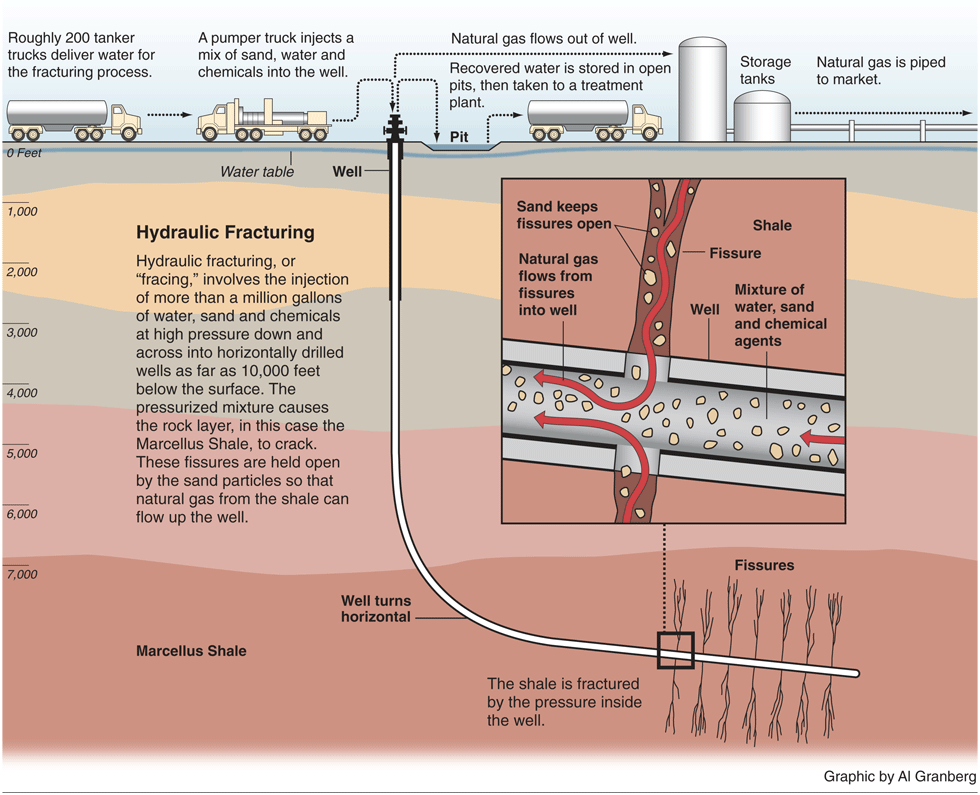
The US Energy Information Administration estimates that US potential natural gas resources total 2543 trillion cubic feet (tcf), with shale gas deposits contributing 862 tcf (34 percent) of this total. At 2010 consumption rates (about 24.1 tcf), the estimated reserve could supply more than 100 years of use. In the eastern US, the Marcellus shale formation extends from New York through Pennsylvania, western Maryland, virtually all of West Virginia, and includes portions of western Virginia and eastern Ohio, and is generally 4000-8500 ft below ground surface. This is far below the aquifers that supply well-water for drinking. It is estimated by researchers Terry Englander, a geoscience professor at Pennsylvania State University, and Gary Lash, a geology professor at the State University of New York, to contain about 50 tcf of recoverable natural gas.
As with any resource extraction activity, concerns have been expressed regarding the procedures used and their actual or potential environmental impacts. In the case of shale gas production, a major concern is related to the hydraulic fracturing used to open cracks in the shale which allow the natural gas to be more efficiently collected. A central focus is on both the volume of water needed for the “fracing” process, the chemicals used, and the potential for groundwater contamination and spills of the waste water water to surface streams and rivers.
The hydraulic fracturing process injects water, sand, and other ingredients at very high pressure into the well. The high pressure creates small fractures in the rock that extend out as far as 1,000 feet away from the well. After the fractures are created, the pressure is reduced. Water from the well returns to the surface (known as flowback), but the sand grains remain in the rock fractures, effectively propping the fractures open and allowing the gas to move. Most frac fluid used in shale gas wells consists of water, a proppant (generally sand), a friction reducing agent (to help the flow-back water return from the well at the end of the frac job), and other chemicals used to protect the well and to optimize performance.
The US Department of Energy estimates that for a typical well in the Marcellus formation, 80,000 gallons of water are needed for well drilling, and 3.8 million gallons for fracturing. Water and sand comprise more than 98 percent of the fracing fluid. 30-70 percent of the fracing fluid returns to the surface as flowback. Thus, there is a large volume of contaminated water from each natural gas well that must be treated in some fashion.
In my next post, we’ll review recent innovations found in Way Better Patents Water Index that apply to the water used in hydraulic fracturing operations.
Thursday, March 8, 2012
patentECO - Wind & Water
 |
| US Patent 6,023,105 |
Grid energy storage, or large-scale energy storage, if you prefer. It’s one of the phrases you hear bandied about in discussions of alternative energy, solar and wind power, and other forms of non-continuous energy generation and refers to ways of storing electricity on a large scale within a power grid. The only currently available, fully operational, efficient, and widely used grid storage technology is pumped storage hydroelectricity.
Hydropower produced 31 percent of the total renewable energy consumed in the US in 2010, according to the US Energy Information Agency. Wind produced 11 percent. What would happen if you coupled water and wind energy generation technologies?
Wasfi Youssef (Mamaroneck, NY) obtained patent number 6,023,105, “Hybrid wind-hydro power plant,” on February 8, 2000. The patent is classified as a prime-mover dynamo plant including a fluid-current motor (290/54). There are currently (early January 2012) 749 patents in this innovation space within the patentECO Energy Index.
Claim 1 states:
“A hybrid wind-hydro power plant in which a difference between two water levels is utilized to generate an electrical power, comprising:
a first water reservoir located at a high level;
a second water reservoir located at a low level;
an equipment for pumping water from said second low reservoir to said first high reservoir consisting of: (a) a water pump positioned in said second reservoir for pumping water to said first reservoir, (b) a penstock from said pump to said first reservoir, which has a non-return valve to allow water flow upstream but not downstream, and (c) a windmill with a rotational shaft coupled directly to said water pump to rotate said water pump and act as a prime mover for said water pump;
a hydraulic turbine installed to receive water via penstock from said first reservoir and to discharge said water to said second reservoir and to convert said water's kinetic energy into mechanical energy of turbine rotation;
an electrical generator coupled to said turbine and rotated by said turbine to produce electrical energy.”
Youssef intends that wind-driven pumps lift water from downstream, or the tailwater area of a hydropower station, to upstream, or headwater. An adjustable weir constructed downstream the water pump holds the water discharged from the turbine and creates a pool or lake from which water can be pumped. The weir can be lowered or raised, allowing the water flow can be managed to suit the wind and the hydropower plant operation.
Another application of his invention is at sites where the wind is strong and there are two nearby waterbodies separated in elevation. The wind-driven water pumps lift water from low elevation to high elevation, where it is stored until used by the hydropower plant to generate electricity. In this application, a hydropower plant is needed, but a dam and adjustable weir are not needed.
Any type of windmill can be utilized, although a vertical-axis type is preferred by the inventor to a horizontal-axis windmill. The former requires fewer connecting components and its tower is much smaller than that of the horizontal-axis type. On the other hand, the horizontal-axis type can be built in larger units and can be more efficient.
The world’s largest pumped hydro facility lies in Bath County, VA, and generates 3,003 MW of power for Dominion. In recent years there has been much interest expressed by wind energy developers to create large mountain-top wind farms in that part of Virginia and adjacent West Virginia. Will the Bath County pumped storage station become a water and wind hybrid?
Tuesday, March 6, 2012
patentECO - Lots of Holes

Four Thousand Holes
“I read the news today oh boy
Four thousand holes in Blackburn, Lancashire
And though the holes were rather small
They had to count them all . . .”
These lyrics, by John Lennon and Paul McCartney, from the last verse of “A Day in the Life” on the classic 1967 album Sgt. Pepper’s Lonely Hearts Club Band, were inspired by an article they read in the January 7, 1967 UK Daily Mail about . . .
. . . potholes.
Much of the U.S. will soon be moving into pothole repair season. What a treat it is to hit one at speed in traffic on an interstate. Potholes are pretty mundane, but represent a non-trivial source of annual vehicle repair costs to US motorists. A 2009 report by the the American Association of State Highway and Transportation Officials, and TRIP entitled “Rough Roads Ahead, Fix Them Now or Pay for It Later” estimates that rough roads add $335 annually to typical vehicle operating costs, and may be as high as $746 in urban areas with high concentrations of rough roads.
So what does the Beatles’ song “A Day in the Life”, and a report about rough roads have to do with patentECO and clean technology innovations?
Three patents, as examples.
Patent number 6,984,670, “Recyclable composite materials articles of manufacture and structures and method of using composite materials,” was issued on January 10, 2006 to John J. Meyers, III (Penfield, NY), John H. Swartz (Coraopolis, PA), and Nathaniel G. and Matthew J. Kurczewski (Moon Township, PA) and assigned to Ace Tire & Parts, Inc. (Coraopolis, PA). The patent is classified (521/50 with other inventions that deal with a process of treating scrap or waste product containing solid organic polymer to recover a solid polymer therefrom, which lies within a broad class accepting synthetic resins or natural rubbers.
The invention uses a composite material using recyclables (glass, polymers, plastics, rubber, both fiberglass and asphalt roof/siding shingles, coal combustion by-products, metals) and that does not contain newly added petroleum products or new, non-recycled chemicals. This material may be used to fill potholes in asphalt and concrete pavement, fill manhole cover recesses, to make expansion joints in roadways, and in building materials, such as, for example, building blocks, structural panels and other structural elements including pipes and fixtures.
Patent number 6,652,185, “Fast efficient permanent pavement repair material system,” was issued on November 25, 2003 to William D. Frey of Leawood, KS. Frey’s invention can be found with others that provide a reinforced structure in a road structure, process, or apparatus (404/70).
Frey’s innovation provides a repair composite for pavement and pothole repair. The repair composite is composed of an a polyester casting resin premixed with dry silica sand, cobalt in combination with dimethylanaline, and a catalyst. How is this clean tech? According to the invention summary, “[t]he use of this composite will eliminate the use of most of the heavy equipment normally used in road repair.”
Patent number 6,588,973, “Pavement method and composition with reduced asphalt roofing waste,” was invented by James S. Omann (Rogers, MN), and granted on July 8, 2003. The invention deals with pavement aspects of a road structure, process, or apparatus (404/17).
Omann has invented a method of manufacturing and applying a novel pavement and patch material for roadways, driveways, walkways, patch for potholes and like surfaces, including the steps of reducing recycled asphalt roof waste to granules, adding aggregate and other solid recyclable materials to the granules, adding rejuvenating oil, adding emulsifier, adding asphalt concrete oil, adding anti-strip additives, adding liquid silicone, mixing the composition, heating the composition, applying the composition to the roadway or the like and compacting a new paving material.
These inventions fall within the recycling aspect of the patentECO Industry Index, but also within the road construction materials and techniques components of the Transportation Index.
And the lyrics at the top of this piece are found within the great music index.

Subscribe to:
Posts (Atom)