Showing posts with label USPTO Green Tech Pilot Program. Show all posts
Monday, February 11, 2013
Capitalism at Work
On January 7, 2013 Acuity Brands, Inc. (NYSE: AYI), a producer of energy-efficient lighting and controls, announced the acquisition of assets of Adura Technologies, Inc., which developed wireless controls and energy management solutions. Adura is a university spin-out of the University of California, Berkeley Center for the Built Environment.
Acuity Brands is, "one of the world’s leading providers of lighting solutions for both indoor and outdoor applications. With fiscal year 2012 net sales of over $1.9 billion, Acuity Brands employs approximately 6,000 associates and is headquartered in Atlanta, Georgia with operations throughout North America, and in Europe and Asia. The company’s lighting solutions are sold under various brands, including Lithonia Lighting®, Holophane®, Peerless®, Gotham®, Mark Architectural Lighting(TM), Winona® Lighting, Healthcare Lighting®, Hydrel®, American Electric Lighting®, Carandini®, Antique Street Lamps(TM), Tersen®, Sunoptics®, Sensor Switch®, Lighting Control & Design(TM), Synergy® Lighting Controls, Pathway Connectivity(TM), Dark to Light®, ROAM®, RELOC® Wiring Solutions, and Acculamp®." Audura's wireless energy management inventions look like a good addition to Acuity Brand's portfolio and may help accelerate wider adoption of LED and OLED solutions.
Adura holds four US patents 7,839,017; 7,925,384; 8,275,471; 8,364,325, with several granted from the US Patent and Trademark Office’s Green Technology Pilot Program. You can learn more about wireless lighting controls and how it was used at two UC Berkeley libraries here.
Audura is a Young Gun - a new and emerging entrepreneurial firms that bring new business models, new products, and new ideas to market. On the innovation, invention, and intellectual property front, Young Guns are the firms to watch. They are where talent scouts, corporate merger & acquisitions pros should look for opportunities for future growth; where investors, venture capitalists, economic and real estate developers looking to attract talent to their cities can find the best scientists, innovators and researchers. Young Guns are the engines of new economic growth and new markets.
Young Guns pursue patents to protect their innovations and product pipeline, attract investors, and accelerate market entry and expansion. It looks like Audura has the qualities sought by the designers of the Green Tech Pilot Program - good technology, patents granted quickly enough to protect markets more strongly than patent applications along, and commercialization of research done as part of university/industry partnerships.
Way Better Patents’ Green Tech Pilot Program Discovery and Analysis Report provides an in-depth review of technology and companies earning patents under the accelerated examination program for "economically important technology". It is a valuable shopping list for investors looking to expand their green technology investments.
Labels:
Acuity Brands,
Adura Technologies,
capitalism,
LED OLED lighting,
USPTO Green Tech Pilot Program,
Young Guns companies
Tuesday, February 5, 2013
A Post on IPWatchdog
An article on Way Better Patents' USPTO Green Technology Pilot Program Discovery and Analysis Report and our findings appeared on Gene Quinn's IPWatchdog blog yesterday. Thanks to Gene for spreading the word on our analysis of the USPTO Green Technology Pilot Program and the interesting outcome on this accelerated examination initiative.
As noted in the post, the Leahy-Smith America Invents Act enables the Director of USPTO to designate "economically important" technology for accelerated examination without having to pay the usual accelerated fees with the goal being to accelerate the commercialization of these inventions. The Green Tech report and analysis provides IP strategists, patent policy researchers, and patent prosecution pros with insight into the outcomes of such a program, who participated, and the inventions that were protected faster. Green technology is a strong candidate for continued accelerated examination in light of the Obama Administration's renewed focus on climate change and alternative energy. We continue to report on the balance of the patents accepted under the program as they move through the prosecution process.
You can learn more about the USPTO Green Tech Pilot Program and the report here.
As noted in the post, the Leahy-Smith America Invents Act enables the Director of USPTO to designate "economically important" technology for accelerated examination without having to pay the usual accelerated fees with the goal being to accelerate the commercialization of these inventions. The Green Tech report and analysis provides IP strategists, patent policy researchers, and patent prosecution pros with insight into the outcomes of such a program, who participated, and the inventions that were protected faster. Green technology is a strong candidate for continued accelerated examination in light of the Obama Administration's renewed focus on climate change and alternative energy. We continue to report on the balance of the patents accepted under the program as they move through the prosecution process.
You can learn more about the USPTO Green Tech Pilot Program and the report here.
Thursday, January 31, 2013
LED Lighting - The Future?
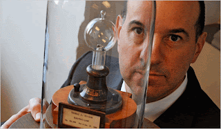
![]() |
| Source: NY Times |
The quintessential symbol of an idea is the incandescent light bulb. No less a purveyor of ideas than the US Patent and Trademark Office (USPTO) pushes a lightbulb icon to the tab on your browser when you visit their web pages and a flag embossed lightbulb as the logo for the America Invents Act. Director David Kappos displays one of Thomas Edison’s original light bulb models in his office. The incandescent light bulb was a truly disruptive and transformative invention that has been used by billions of people worldwide.
The US Energy Information Administration (USEIA) estimates that in 2012 US residential and commercial lighting used 13 and 20 percent, respectively, of the electricity purchased in those energy use sectors (USEIA Annual Energy Outlook 2013 Early Release, reference case). Thus, lighting represents a major opportunity for reducing energy use via technological changes (e.g., compact fluorescent bulbs, LEDs, automated controls), behavioral changes (e.g., energy conservation programs), or government laws and regulations that incrementally ban the manufacture and sale of a more than century-old lighting technology.
The USPTO Green Tech Pilot Program issued a significant number of lighting-related patents. We’ll look at some of those representative of inventions by one of the dominant assignees in the program.
LG Innotek
LG Innotek (011070:Korea SE), headquartered in Seoul, Korea, was “the first general electronic component company in Korea”, according to the company’s web page. The company manufactures and sells LED lighting, printed circuit boards, mobile devices such as digital camera modules, electronic display components, network and automotive devices.
Some LED Patents
Three patents are representative of some of LG Innotek’s LED technology.
The Single LED Package
Light emitting diodes (LED) are semiconductors that convert electricity into light. Once used almost exclusively as indicator lighting for electronics, solid state LED lighting is a rapidly emerging technology that continues to move into the mainstream of general purpose illumination technology.
Early energy inventions in lighting, and specifically light emitting diode technology, reach back to 1907. LEDs operate based on electroluminescence — where a material emits light in response to an electrical current or a strong electric field. The phenomenon was discovered in 1907 by British researcher H. J. Round.
Source: USPTO Green Technology Program Discovery and Analysis Report, Way Better Patents.
A good example of a typical LED is found in LG Innotek’s US 8,039,863 patent, ‘Light emitting device’, issued on October 18, 2011. The single inventor is Bum Chul Cho.
Claim 1 is a concise summary of the invention:
A light emitting device comprising:
a package body comprising a trench;
a first electrode and a second electrode on and/or in the package body;
a wire electrically connected to the second electrode;
a light emitting diode on the first electrode, the light emitting diode being electrically connected to the second electrode through the wire; and
a lens on the package body and covering the wire, wherein at least one of the first electrode and the second electrode extends up to a bottom surface of the package body via the trench disposed in the uppermost surface of the package body.
Many multiples of these individual packages make up LEDs you might purchase in your local big-box store, in stop lights (that in winter have difficulty in snowy weather because they don’t generate sufficient heat to melt snow and ice. There are always unintended consequences; for example, (see our post patentECO - The Unintended Consequences of Inventions) or that would be found in the next two patents below.
A LED With Sand
Patent US 8,115,369, ‘Lighting device’, issued on February 14, 2012 to Seok Jin Kang and three co-inventors. Filed on November 8, 2010, its three-year plus prosecution was significantly longer than the 19.7 month average from the program up to that point (a detailed review of pendency under this demo ‘economically important technology’ program may be found in Way Better Patents Discovery and Analysis Report.)
Claim 1 shows the use of the major component of sand in a heat transfer pad between the light emitting substrate and a heat sink:
A lighting device comprising:
a substrate;
a light emitting device disposed on the substrate;
a heat sink to radiate heat from the light emitting device;
and a pad being interposed between the substrate and the heat sink and transferring heat generated from the light emitting device to the heat sink and comprising silicon of 10 to 30 wt° A, a filler of 70 to 90 wt %, glass fiber of 2 to 7 wt % in terms of weight percent (wt %), wherein the light emitting device includes an LED.
The sand-based (i.e., silicon) heat transfer pad and heat sink are necessary to reduce heat generated from the device.
A LED for Your Shop
How many of you have ceiling mounted multiple-tube fluorescent light fixtures in your kitchen, garage, workshop, rec room (does anyone have those anymore, or have they all become ‘media rooms’?), office, or store? LG has a light for you.
Patent US 8,109,647, also entitle ‘Lighting device’, issued on February 7, 2012 to Kim Dong Soo and Kim Yun Ha. This patent issued in less than 18 months, faster than the Green Tech program average pendency.Claim 11 provides a good summary of the invention:
A lighting device comprising:
a case comprising:
a bottom plate;
walls extending from ends of the bottom plate; and
louvers coupled to and inclined from respective edges of the walls;
a light emitter coupled to the bottom plate;
a diffuser plate spaced apart from the light emitter and disposed between the walls, and a reflector, disposed on an inner surface of the case, to reflect light emitted from the light emitter and to direct the reflected light through the diffuser plate, wherein each of the louvers is oriented at an obtuse angle relative to the diffuser plate and wherein the light emitter includes an LED.
Market Opportunity
Other companies in the LED innovation space include Cree, Philips, Osram, and GE among others. They are aware of the great market potential of LED lighting, as described by the US Department of Energy:
Widespread use of LED lighting has the greatest potential impact on energy savings in the United States. By 2027, widespread use of LEDs could save about 348 TWh (compared to no LED use) of electricity: This is the equivalent annual electrical output of 44 large electric power plants (1000 megawatts each), and a total savings of more than $30 billion at today’s electricity prices.
That’s a good thing, because recent USEPA regulations caused the retirement of more than 9,000 MW of coal-fired power plants in the US in 2012 and could eventually lead to the closing of almost 35,000 MW of coal electricity generation.
Thursday, January 24, 2013
Freight Train - Clean Tech
Freight Train
“Blow Your Whistle Freight Train” was an early classic of American country and bluegrass music, performed by groups as wide ranging as The Delmore Brothers, Hank Snow, Clarence White, The Grateful Dead, Doc Watson, Nitty Gritty Dirt Band, and by front porch and shade tree pickers such as my Uncle John and myself.I’d rather be in some dark hollowAnd then there was Elizabeth Cotten’s “Freight Train”, also performed by a wide range of musicians including Peter, Paul, and Mary, Joan Baez, Jerry Garcia and David Grisman, and your correspondent and his uncle:
Where the sun don’t ever shine
Than to be home alone and knowing that you’re gone
Would cause me to lose my mind.
So blow your whistle freight train
Take me far on down the track
I’m goin’ away I’m leavin’ today
I’m goin‘, but I ain’t comin’ back.
Freight train freight train goin’ so fastOne of the first songs I learned to play.
Freight train freight train goin’ so fast
Please don’t tell what train I’m on
So they won’t know where I’ve gone.
So what does this have to do with clean tech?
Railroads have been a major force in American westward expansion, economic development, transportation, and culture for close to 200 years. They continue to move massive quantities of freight, but far fewer passengers. They provide a highly fuel efficient means of land transportation, and offer opportunities for innovation to produce more efficiencies. Hence, the connection.
Union Pacific Railroad
Union Pacific (NYSE: UNP), headquartered in Omaha, Nebraska, is the largest rail network in the US. Founded on July 1, 1862 with the signing of the Pacific Railroad Act by President Abraham Lincoln, the company was directed, along with the Central Pacific, to construct a transcontinental railroad. Seven years later the ‘Golden Spike’ was driven at Promontory, Utah, completing the cross-country line and inaugurating its use. Today the railroad has a fleet of more than 8,000 locomotives, travels in 23 states from Tennessee to the West Coast and the Canadian to Mexican borders on more than 32,000 miles of track, and employees 45,000. According to the company’s 2011 Fact Book, the railroad moved 978,163 gross ton-miles of freight, using 1,106 million gallons of fuel, had an average train speed of 25.6 mph, and an average inventory of 272,900 rail cars. UP’s freight revenue was obtained from energy (2%), intermodal (20%), agricultural (18%), industrial products (17%), chemicals (15%), and autos (8%).Intermodal?
Shipping containers and over-the-road trailers are often shipped long distances via rail, mixing different modes of freight transportation, hence, ‘intermodal’.Rail transportation of freight is three times more fuel efficient than moving the same freight on the highway. A ton of freight can be moved 450 miles on one gallon of fuel (e.g., diesel) via rail. Even though this is a very fuel efficient mode of land transport, railroads are constantly working to improve their fuel efficiency. One of the ways this is being carried out is through improvements to railroad locomotives. For example, see our posts here and here on a new fuel cell locomotive. The latter post contains a photo taken at the Golden Spike National Historic Site.
Another approach to increased fuel efficiency is modifications to the rolling stock.
Remember Aerodynamic Locomotives? Intermodal Container Cars Join Them
Does anyone remember the aerodynamic train engines of days gone by, particularly those from the 30s–50s?Inventor Michael Iden was awarded patent US 8,215,239, ‘Aerodynamic pseudocontainer for reducing drag associated with stacked intermodal containers’, on July 10, 2012 from the USPTO Green Tech Pilot Program. Union Pacific benefitted from the accelerated examination offered by the program, receiving the patent slightly more than 18 months after initial filing.
Iden’s abstract provides a succinct, understandable summary of his invention:
Disclosed is an aerodynamic pseudocontainer for a train. The pseudocontainer is configured to be stacked atop an intermodal container in a lead container car at a lead end of the train, so that its aerodynamic configuration reduces drag when the train is in motion, thereby reducing fuel costs and emissions. The pseudocontainer may have connectors on its bottom so that when it is placed on top of the intermodal container, locking devices may be used for attachment.This is illustrated by one of the patent drawings, and the photo showing the testing of Union Pacific’s ‘aerowedge’ prototype in August 2012.
A Historical Connection
The earliest patent citation on Iden’s ‘239 patent is US2,253,209 granted to John W. Patton on August 19, 1941 and assigned to the Edward G. Budd Manufacturing Company of Philadelphia. Patton recognized that “it is desirable to provide a rounded end on the last car of the train.” This led to a railroad efficiency problem (i.e., an unintended consequence of innovation) because it meant that the last train car was a very different configuration than the others in the train, resulting in the need “to turn the train around at each of its terminals in order to prepare it for its return run.” This was found to be impractical, and Patton developed his solution:One object of the present invention is to solve this problem by providing a streamlined casing for removable attachment to the tractor unit of the train, so that the tractor unit may be connected to the rounded end of a car and still preserve the streamlined appearance of the train.His removable streamlining attachment, showing in an accompanying drawing, is a direct antecedent of Union Pacific’s new “Aerowedge” attachment for intermodal freight cars.
![]() |
| Source: triplepundit.com |
Saturday, January 12, 2013
Another US Solar Firm Sold To The Chinese
Another Young Gun that benefitted from the USPTO Green Technology Pilot Program's accelerated examination program has been sold to a Chinese company.
On January 10th, 2013 MiaSole, founded in 2003, announced that Hanergy Holding Company of China has acquired the company and its technology for a fraction of the funds the start-up received from its investors. Investors put $550 million into the firm. Hangery is paying about $30
MiaSole's received patents US 7897020 , US 7829783 and US7960643 under the green tech program. MiaSole's thin film products, called CIGS technology, use copper, indium, gallium and selenide. This technology is lighter than traditional silicon based products and can be layered between sheets of glass that can be used as tinted windows on a building or integrated into flexible material for use on rooftops.
What Solar Tech Do The Chinese Get This Time?
Here's a partial list of the intellectual property that the Chinese get this time. It doesn't include trade secrets or pending patent applications. This is a significant portfolio of thin film solar technology and methods for making those products.
What Solar Tech Do The Chinese Get This Time?
Here's a partial list of the intellectual property that the Chinese get this time. It doesn't include trade secrets or pending patent applications. This is a significant portfolio of thin film solar technology and methods for making those products.
| PAT. NO. | Title | |
|---|---|---|
| 1 | 8,342,229 | Method of making a CIG target by die casting |
| 2 | 8,338,214 | Sodium salt containing CIG targets, methods of making and methods of use thereof |
| 3 | 8,329,496 | Dithered scanned laser beam for scribing solar cell structures |
| 4 | 8,227,287 | Partially transmitted imaged laser beam for scribing solar cell structures |
| 5 | 8,203,200 | Diode leadframe for solar module assembly |
| 6 | 8,134,069 | Method and apparatus for controllable sodium delivery for thin film photovoltaic materials |
| 7 | 8,123,565 | External electrical connectors for solar modules |
| 8 | 8,115,095 | Protective layer for large-scale production of thin-film solar cells |
| 9 | 8,110,738 | Protective layer for large-scale production of thin-film solar cells |
| 10 | 8,076,174 | Method of forming a sputtering target |
| 11 | 8,062,384 | Systems, methods and apparatuses for magnetic processing of solar modules |
| 12 | 8,058,752 | Thin-film photovoltaic power element with integrated low-profile high-efficiency DC-DC converter |
| 13 | 8,048,707 | Sulfur salt containing CIG targets, methods of making and methods of use thereof |
| 14 | 8,048,706 | Ablative scribing of solar cell structures |
| 15 | 8,017,976 | Barrier for doped molybdenum targets |
| 16 | 8,004,232 | Method of battery charging and power control in conjunction with maximum power point tracking |
| 17 | 7,963,802 | External electrical connectors for solar modules |
| 18 | 7,960,643 | Isolated metallic flexible back sheet for solar module encapsulation |
| 19 | 7,935,558 | Sodium salt containing CIG targets, methods of making and methods of use thereof |
| 20 | 7,927,912 | Method of forming a sputtering target |
| 21 | 7,897,020 | Method for alkali doping of thin film photovoltaic materials |
| 22 | 7,838,763 | Manufacturing apparatus and method for large-scale production of thin-film solar cells |
| 23 | 7,829,783 | Isolated metallic flexible back sheet for solar module encapsulation |
| 24 | 7,785,921 | Barrier for doped molybdenum targets |
| 25 | 7,544,884 | Manufacturing method for large-scale production of thin-film solar cells |
| 26 | 6,974,976 | Thin-film solar cells |
Tuesday, December 18, 2012
Curious Green Tech Patents - SUV Tents
The curious patents issued by the USPTO’s Green Technology Pilot Program continue with US 8,230,870, issued on the last day of July, 2012. “SUV tent traveler” was invented by Robert D. Horejsh of Altoona, WI. The patent abstract provides a summary:
"An elevated floor camper tent for SUV (Sport Utility Vehicle) type vehicles having electric, hybrid or other energy-saving, lower horsepower engines and top hinged rear doors. The entire tent assembly fits inside the vehicle for aerodynamic maximization and the state-of-the-art materials minimize the total weight. A set of continuous slides provides support and, with integrated footpads, facilitates setup on hard or soft surfaces. The campers sleep within the relative safety of the vehicle and utilize the main part of the tent as a living area. The standard features, under actual test conditions, suggest the design as safe, effective and user-friendly plus the stable, framed living area having built in rail-type support braces and kick panels help prevent the users from accidents."The specification of a patent is the “written description of the invention and the manner and process of making and using the claimed invention.” Much useful information can be found there, and for clean tech inventions particularly inventors’ statements regarding why they think their innovation is clean tech.
The spec of the ‘870 patent contains several statements of Horejsh’s intent:
- The higher-mileage, hybrid and electric vehicles could be utilized for camping thus enhancing their versatility and general usage in the camping community. Our camper-tent invention is designed from the ground up to be specifically used by the vehicles of now and in the future.
- The “SUV Tent Traveler” (name used for identification purposes only) is a concept of a tent, tent frame, elevated camper floor contained entirely within the vehicles’ storage area and mounted on continuous slides.
- Earth-friendly vehicles are limited for camping although we purchased a Ford Escape Hybrid knowing the towing capacity was only 1,000 lbs. (passengers and cargo included). What we didn’t know was that already optimistic rating was based on a flat surface at lower altitudes and campers under 1,000 lbs. were barely available, those being very expensive. Alternatives involved roof top units with a MPG robbing aerodynamic drag; mini trailers with the inherent problems of pulling another object; and tents, set directly on the ground with a boot to connect to a vehicle. We found the vehicle rear area too short to comfortably sleep in so, in effect, that alternative (attached ground tent) was really just camping out. Earth-friendly vehicles include hybrid, electric, enhanced, dual or multiple mode-powered vehicles, or generally any vehicle with lower rated horsepower for higher MPG, designed by the manufacture to save energy through aerodynamic design with top hinged rear doors.
- The key to its uniqueness is a continuous flat plane slide system comprised of a plurality of sections adjacent to each other to extend the main floor panel longitudinally out from under the cargo floor panel.
The tent does not decrease vehicle weight (to the contrary, it increases weight).
The SUV tent does not increase vehicle fuel efficiency (it decreases it since it represents extra weight).
It does not improve vehicle aerodynamic form (it’s stored within the vehicle except when set up (during which time the vehicle is not traveling and incurring aerodynamic friction), just as your normal, everyday pup tent would be).
The invention is classified under CLASS 135, TENT, CANOPY, UMBRELLA, OR CANE.
The patent has only two claims.
The time between filing and grant was less than a year, short even by Green Tech program standards.
And what about the prior art? A walk around Bonnaroo (or a look at the photo stream of the parking/camping area) or a visit to a college football tailgate will yield lots of prior art small SUV tent configurations.
This invention is from an independent inventor who generally have a harder time commercializing their inventions even if accelerated patenting is helpful. We'll skip the the intent of the program to "accelerate the development and deployment of green technology, create green jobs, and promote U.S. competitiveness in this vital sector." (See the press release announcing the program here.)
This type of interpretation of what is within the boundaries of an accelerated examination program should provide interesting material to innovation researchers in light of upcoming changes under the America Invents Act that enable the Director of USPTO to designate "economically important" technology.
Another curious patent granted under the Green Tech Pilot Program.
Labels:
car tents,
patentECO,
USPTO Green Tech Pilot Program
Tuesday, December 11, 2012
The Curious Case of Green Tech Bolts
A recent post covered General Electric receiving a patent from the US Patent Office’s Green Technology Pilot Program for a wind turbine doorway. When I initially ran across the patent, I halfway jokingly told a colleague “Makes me wonder whether the bolts that are used to hold the door to the door frame are also considered green tech.” Little did I know at the time …
Exactly three weeks later, USPTO granted GE and inventor Denis Heide (Munster, Germany) US 8,186,923, “Connecting arrangement and method of fastening a bolt.”
The abstract provides a summary:
A connecting arrangement is provided. The connecting arrangement includes a bolt with a fastening portion at one end thereof, which has one or more grooves; a cotter having a conical shape and one or more convex cuts on the inner side of the cotter adapted for fitting with the one or more grooves of the fastening portion of the bolt; two support blocks, each having a thread on the outer side, wherein at least one of them is on the inner side adapted for fitting to the conical shape of the cotter; and a fastener having a thread on the inner side, wherein the fastener is adapted for being screwed on the support blocks.Claim 1 provides some excellent patent-speak:
A connecting arrangement, comprising:What does this have to do with clean tech? According to the Background of the Invention, “Especially in very large applications, such as wind energy systems, the screw connection has to meet high security demands. The flange connections of wind energy systems are also screwed and the required strength is achieved by using large screws.”
a bolt including a fastening portion including one or more grooves, whose circumference is differentiable between at least two portions;
a cotter including at least two parts and including an essentially conical shape on the outer side and a axial bore when the at least two parts are put together, wherein the axial bore provides one or more convex cuts on the inner side of the bore, wherein the convex cuts are adapted for fitting with the one or more grooves of the fastening portion of the bolt;
at least one first support block including a thread on the outer side;
at least one second support block including a thread on the outer side, wherein the at least one second support block is on the inner side adapted for fitting to the conical shape of the cotter;
and a fastener including a thread on the inner side, wherein the fastener is adapted for being screwed on the support blocks.
Curiously, the same sequence of events occurred for this ‘923 patent as for the ‘674 patent - the filing of the Petition to Make Special, some volleying back and forth with the examiner and then, USPTO miraculously, accepting the petition. In this case, GE submitted the petition to USPTO on July 12, 2011. The same Tech Center 3600 QA Specialist dismissed the petition on July 22, 2011. Once again, item 4 requirements were the basis of the Tech Center dismissal. The detail continues a theme we saw in the ‘674 doorway patent:
In regard to item 4, the claimed bolt-nut/connecting system for being used in a wind energy system would not materially contribute to the development of renewable energy resources or energy conservation since the bolt-nut/connecting system cannot generate energy or convert the mechanical energy into electrical energy. It is unclear which part of the bolt/connecting system conserves energy. A bolt-nut/connecting system plays no role in the operation of the wind energy system. In addition, as the claimed bolt-nut/connecting system and the resulting support structure may not necessarily be used in a wind energy system, petitioner’s assertion of the bolt-nut/connecting system’s contribution to the development of renewable energy resources or energy conservation is entirely speculative. As stated in the notice, the materiality standard does not permit an applicant to speculate as to how a hypothetical end-user might specially apply the invention in a manner than [sic] could materially contribute to category (A) or (B). Also see MPEP §708.02 (VI). Accordingly, it is not agree that the application on its face meets that materiality standard.(emphasis added)
GE filed a Request for Reconsideration on August 24, 2011 which contained some artful linguistic gymnastics on why a bolt is critical to green energy. This time they,
"respectfully submit[ted] that the Federal Registry does not require that an invention generate energy or convert mechanical energy into electrical energy in order to materially contribute to the development of renewable energy resources or energy conservation. … Embodiments of the present invention materially contribute to the development of renewable energy by providing an arrangement and methods of fastening a bolt that increases the fatigue resistance of a connection in wind energy systems. These measures increase the availability of wind energy as a viable power generating option by reducing maintenance and decreasing costs, and also by reducing wind turbine down time. As a result, embodiments of the present invention promote increased energy production, and thus materially contribute to the development of renewable energy resources or energy conservation.However, here is text from Federal Register 74FR64666 (found in section III of the Notice) which seems to undercut GE’s argument:
Patent applications are also eligible for the Green Technology Pilot Program if the applications are for inventions that materially contribute to: (1) The discovery or development of renewable energy resources; (2) the more efficient utilization and conservation of energy resources; or (3) the reduction of greenhouse gas emissions. The term “renewable energy resources” for purposes of the procedure specified in this notice includes hydroelectric, solar, wind, renewable biomass, landfill gas, ocean (including tidal, wave, current, and thermal), geothermal, and municipal solid waste, as well as the transmission, distribution, or other services directly used in providing electrical energy from these sources. [emphasis added]Admittedly, this wording is somewhat open-ended, but “development of renewable energy resources”, and the last emphasized clause, strongly suggest that USPTO did not intend the connection and fastening of bolts to be considered eligible under the program. This is supported by the wording of their petition dismissal.
No matter, however, as the USPTO accepted GE’s arguments and granted their petition on September 29, 2011. This decision was also signed by the same Tech Center 1700 QA Specialist as the corresponding one for the ‘674 patent.
Did we mention that as of May 29, 2012, the date of the ‘923 bolt patent, the USPTO Green Tech Pilot Program had granted 213 GE patents, out of a total of 1126 issued, or 18.9%? GE’s next closest competitor in terms of total program patent grants through May 29 was Ford Motor Company, and its subsidiary Ford Global Technologies, LLC, with 108 patents (9.6%). Certainly, GE has very successfully used the Green Tech Pilot Program to reduce the pendency of its clean tech inventions over the past few years. Given GE’s vast patent portfolio (more than 37,000 as of November 6, 2012), IP prosecution experience, and very large IP staff, these results are not surprising.
Tuesday, December 4, 2012
Doorway To Green Technology - Green Tech Doorway
![]() |
| A clean tech door: the doorway 102, a doorway frame 106, a doorway opening 122, and an outer face 134. |
Curious Green Tech Program Patents - #1
While reviewing patents issued under the USPTO’s Green Technology Pilot Program], I was struck by the title of US 8,171,674 – “Doorway for a wind turbine tower.”
A doorway receives a green tech/clean tech patent from the US Patent Office?
First, details on the ‘674 patent, issued in early May 2012. The inventors – Bharat Bagepalli of Niskayuna, NY and Russell Earle Walthers, from Saratoga, CA. The assignee – General Electric Company. The technology, according to USPTO, static structures including a component designed to receive a disparate article having disparate article mounted thereto on shaft or tower. Isn’t government-speak great?
In other words, an object (in this case, a doorway) mounted on a tower. The abstract:
A doorway for a tower of a wind turbine is disclosed. The doorway may generally comprise a doorway frame having a substantially rectangular shape and including an inner face and an outer face. An opening may be defined between the inner and outer faces and may be configured to provide access to an interior of the tower. Additionally, at least one of the inner face and the outer face may define a substantially planar surface along at least a portion of its width.The patent contains 13 claims, of which claim 1 is representative:
A tower for a wind turbine, the tower comprising:Wondering how a patent for a doorway was issued as a green tech/clean tech, a review of the various documents supporting the patent ensued.
a tower segment having a first end and a second end, the tower segment defining a curved shape between said first and second ends; and
a doorway disposed between said first and second ends, said doorway comprising:
a doorway frame having a substantially rectangular shape and including an inner face and an outer face and,
an opening defined through said inner and outer faces, said opening configured to provide access to an interior of the tower,
wherein at least one of said inner face and said outer face defines a substantially planar surface along a substantial portion of its width.
Applicants wishing to have their inventions considered under the US Patent Office’s Green Tech Pilot Program were required to complete a form (it’s government, after all) to specifically request accelerated examination under the program. The inventor duly filed the form (received at USPTO 5/24/11); here is an excerpt:
Applicant respectfully submits that Special Status is sought on the basis that the present invention materially contributes to the development of renewable energy resource or energy conservation.Materially? Do real inventors say materially or is this a lawyer term? In this case it's a USPTO term.
The petition to make special was routed to Art Unit 3633 for a decision. On June 7, 2011, USPTO (a Tech Center 3600 Quality Assurance Specialist, specifically) replied:
The petition is DISMISSED.The Patent Office’s reasoning was that “[t]he petition lacks item 4”. Item 4 in the requirements for achieving Green Tech accelerated exam status was:
If the disclosure is not clear on its face that the claimed invention materially contributes under category (A) or (B) [A) materially enhances the quality of the environment or B) materially contributes to: i) the discovery or development of renewable energy resources, ii) the more efficient utilization and conservation of energy resources, or iii) greenhouse gas emission reduction.] [^1], the petition must be accompanied by a statement by the applicant, assignee, or an attorney/agent registered to practice before the Office explaining how the materiality is met.Additional justification for dismissal was provided by USPTO:
In regard to item 4, the claims are directed to a doorway used in a tower which can be used to support a wind turbine. Since the wind turbine is not claimed, the claimed doorway or tower in and by itself would not ordinarily contribute to the development of renewable energy resources - a doorway or a tower cannot generate energy or convert the mechanical energy into electrical energy. There is no evidence in the present application that the claimed doorway or tower materially contributes to the development of renewable energy resources. In addition, as the claimed doorway or tower would not necessarily result in a tower used to support a wind turbine, petitioner’s assertion of the claimed method’s contribution to the development of renewable energy resources or energy conservation is entirely speculative. As stated in the notice, the materiality standard does not permit an applicant to speculate as to how a hypothetical end-user might specially apply the invention in a manner than [sic] could materially contribute to category 9A) or (B). Also see MPEP §708.02 (VI). Accordingly, it is not agreed that the application on its face meets that materiality standard.This seems to be a very reasoned and well-supported dismissal.
GE disagreed and filed a Request for Reconsideration of the Patent Office’s denial of the request for accelerated examination under the Green Tech Program; this was received by USPTO on June 30, 2011. The heart of GE’s request to reconsider is contained in the penultimate paragraph of their Request:
Embodiments of the present invention materially contribute to the development of renewable energy by reducing the thickness of tower segments required for wind turbines and reducing the time and expense necessary to form the tower doorway. As such, these measures promote investment in wind turbine technology by making it a more cost-effective alternative to other non-renewable energy technologies, which in turn promotes increased energy production.GE is arguing that reducing the thickness of tower segments, and reducing time and expense (to them, the manufacturer) to form a wind tower doorway constitute sufficient reasons for the application to be accepted for accelerated examination under the program. They are arguing here that thinner wind turbine tower segments, and reduced manufacturing time and expense for GE do materially contribute to the development of renewable energy resources or energy conservation. But none of those aspects address either the requirements of Item 4, provided above, under which the accelerated exam request was dismissed, orthe USPTO’s specific, detailed reasoning supporting that dismissal.
On August 4, 2011, USPTO agreed with GE’s request (what a surprise); this time, however, the reply came from a QA Specialist in Tech Center 1700:
The petition is GRANTED.USPTO did not provide any reasoning for supporting their grant of the petition to make special, nor any reasoning to explain why they now viewed GE’s wind turbine doorway as meeting program requirements, when just a few weeks previously they had given a well-written, logical set of reasons for rejecting the application for acclerated examination under the program.
Thus, the bottom line in GE’s and USPTO’s thinking is that a wind tower door is clean tech.
Did we mention that GE has received the largest number of patents of any assignee under the USPTO Green Tech Program? Or that GE was definitively involved in the program prior to its announcement on December 7, 2009? See the USPTO press release announcing the program on that date with a quote from Carl Horton, Chief Intellectual Property Counsel of General Electric, who “hailed the new initiative” (I’m sure he did, considering how well GE subsequently did under the program) ”We hail this initiative as an excellent incentive to fuel further innovation of clean technology and a terrific mechanism to speed the dissemination of these patented technologies throughout the world,” Horton said. ’) Or that Jeffrey Immelt, Chairman of the Board and CEO of GE, is head of the Obama Administration’s Jobs Council (nothing more need be said here?) Representatives from GE introduced their colleague who wrote many of the patent applications and crafted the green tech justifications at the USPTO Green Technology Partnership meeting too.
Inventors, remember, precedent has been established. A doorway is clean tech, if you tie it to a wind turbine. (Improving a the driving experience of an electric vehicle also qualified.)
Amazing. One might think the Office was under some pressure to produce clean tech/clean energy patents from this program. Naahh, that couldn’t be, could it?
[^1] Pretty limited criteria for energy-related clean tech inventions, wouldn’t you agree?
Thursday, November 29, 2012
Electric Motors, New & Old
Several high school students zip by my house in the mornings and afternoons on bicycles with tiny 2-stroke gas engines. I perceive them from a long distance, hear the Doppler effect as they approach and recede, and cringe as they pass the house – the motors may be small, but they are SHOCKINGLY LOUD AND PENETRATING.
Surely there might be a less noisy solution to their desire not to have to pedal? One might ask why bother to ride a bike, but I won’t.
E-bikes (electric bikes) would solve my local students’ need for locomotion, and my, and my neighbors’, need to retain our hearing.
Enter the US Patent Office’s Green Tech Pilot Program, and patent US 8,222,786, issued in July 2012 to David G. Calley and co-inventors, all in Flagstaff, AZ; their patent is assigned to Motor Excellence, LLC.
Their invention is entitled “Transverse and/or commutated flux systems having phase offset”, and is described in the abstract:
"Electrical machines, for example transverse flux machines and/or commutated flux machines, may be configured to achieve reduced overall cogging torque via implementation of a sixth-phase offset. Individual cogging torque waveforms in the electrical machine may be evenly distributed across one-sixth of a voltage phase or other suitable spacing, resulting in a reduced magnitude and/or increased sinusoidality of the overall cogging torque waveform for the electrical machine."In claim 10 one learns that “The stator of claim 2, wherein the stator is coupled to a wheel of an electric bicycle.”
Inventor Calley has 14 patents assigned to Motor Excellence for which he is the first-named inventor; five of these issued from the Green Tech Pilot Program. Four of the Green Tech patents are found in the patentECO Energy | Energy efficiency | Motors & alternators | Design hierarchy (Index | Category | Technology | Feature), and the fifth is categorized as Transportation | Electric vehicle | Motor | Stator. A fascinating aspect of all of Calley’s Motor Excellence (ME) patents is that they cite US 1,361,136 as the earliest citation. In other words, ME’s key technology derives from a patent issued in 1920. The ‘136 patent, “Dynamo-Electric Machine,” “relates to an improved method and form of construction of dynamo electric machines which is especially applicable to comparatively small sizes of motors, generators and the like. The main objects are to simplify the method of construction and reduce the amount of labor necessary and also reduce the cost of material while producing a strong and durable construction with reduction of size and weight of the machine.”
The Motor Excellence web page states:
"Motor Excellence (Me) is an innovative clean technology company that has designed a new class of high-efficiency electric motors for use in a vast range of applications. Unique in their design, Me boldly offers a 21st century answer to a world tied to inefficient, wasteful and polluting 19th century motor technologies. Me motors enable highly efficient, more cost effective and less resource-intensive electric-powered machines, which will ultimately reduce the world’s reliance on unsustainable energy sources."No word on 20th century tech.
The company owns a subsidiary, Me eBike LLC, that “provides motors with unprecedented range, acceleration and hill climbing ability to the global electric bicycle industry. Electric bikes (e-bikes) are two or three wheel pedal-driven bicycles with an electric hub motor that provides propulsion assistance to a rider.”
Motor Excellence, founded in 2007, is one of the Young Gun companies in Way Better Patents’ Discovery and Analysis report on USPTO’s Green Tech Program. They completed a move to new Flagstaff headquarters in 2009, and expanded into additional manufacturing space in 2011. This expansion was funded in part by “a $962,000 grant from the 21st Century Grant Program coordinated by the Arizona Commerce Authority (ACA) in 2009, it hired five new workers the next day. The grant program is designed to utilize federal stimulus funds to invest in and promote energy efficient and renewable energy products manufactured in Arizona,” according to a company press release. The Arizona Daily Sun reported in late December 2011 that Motor Excellence had laid off 24 workers and eliminated one management position in November/December 2011. A cached version of inventor David Calley’s Linkedin profile states that he continued with Motor Excellence to July 2012, when “Motor Excellence’s assets were purchased and the new company is called Electric Torque Machines.” A subsequent patent awarded to Calley and assigned to ETM also reaches back to the 1920 ‘136 patent.
According to Pike Research, the electric bicycle market in the US is expected to triple by 2018 with global sales exceeding 47 million vehicles generating nearly $12 million in revenue. China dominates the global market for e-bikes sales accounting for 92% of the total sales. The US market accounts for only about 89,000 e-bikes this year. (The e-bikes are a popular favorite for food delivery people in big cities.) Sales of e-bikes in the US are expected to reach 265,000 by 2018.
Of course, the ME and ETM patents for electric bike motors refer to many other intervening patents and technologies, as you will see if you review some of them. However, Calley and his co-inventors determined how to improve on an old design in a way that meets USPTO criteria for
- what can be patented (process, machine, article of manufacture, composition of matter, improvement of any of the above)
- novelty
- nonobviousness
- adequately described or enabled (for one of ordinary skill in the art to make and use the invention)
- claimed by the inventor in clear and definite terms.
Labels:
David G. Calley,
ebikes,
Electric Torque Machines,
Motor Excellence LLC,
patentECO Indexes,
prior art,
USPTO Green Tech Pilot Program
Thursday, October 11, 2012
Power From Travel
“Two roads diverged in a yellow wood,In terms of renewable energy, the choice of the road you take could make all the difference.
And sorry I could not travel both …
Two roads diverged in a wood, and I,
I took the one less traveled by,
And that has made all the difference.”
From The Road Not Taken, by Robert Frost
Jack Shihzong Jang of Delaware, OH was granted, on April 24, 2012, patent US 8,164,204.
His invention? “Electrical generator apparatus, particularly for use on a vehicle roadway.” The invention provides
[a]n electrical generator apparatus, which is configured to convert an external actuation force applied by a vehicle traveling on a roadway into electrical energy, [and] includesJang desires to provide “an electrical generator apparatus … designed to capture the otherwise wasted kinetic energy of moving vehicles travelling on a roadway [providing] more efficient use of energy resources. The present invention materially contributes to the efficient utilization and conservation of petroleum-based energy resources by making better use of the energy consumed by vehicles.”
a rotatable top portion adapted to receive the external actuation force applied by the vehicle traveling on the roadway;
a plurality of linkage members operatively connected to one another in succession, the rotatable top portion being operatively coupled to a first one of the plurality of linkage members operatively connected to one another in succession;
a first wheel operatively coupled to a last one of the plurality of linkage members operatively connected to one another in succession;
a second wheel operatively coupled to the first wheel via a tangential coupling element;
a rotatable shaft operatively coupled to the second wheel;
at least one flywheel operatively coupled to the rotatable shaft;
and at least one electrical generator operatively coupled to the rotatable shaft, the electrical generator adapted to convert a rotational movement of the rotatable shaft into electrical energy. The second wheel of the electrical generator apparatus is configured to rotate at a higher angular velocity than the first wheel.
![]() |
| Foot powered grinding wheel |
a plurality of generators wired in parallel is electrically connected to an electrical storage device. The plurality of generators produce direct current (DC) power. In a preferred embodiment, the electrical storage device comprises one or more batteries for storing the electrical energy generated by one or more electrical generator apparatuses. However, in other embodiments of the invention, a different type of electrical storage device could be employed, such as capacitors or ultracapacitors. A voltage regulator for automatically maintaining a constant voltage level is electrically connected to the electrical storage device. On its output side, the voltage regulator is electrically connected to an inverter that converts the incoming direct current (DC) from the voltage regulator into alternating current (AC) for power use. After passing through both the voltage regulator and the inverter, the output power from the electrical generator apparatuses has the same voltage and frequency as the local power grid.Lest you think the idea for generating electrical power from the action of vehicles moving over a roadway is new, check out patents US 3,859,589 (1975), US 3892136 (1975), US 3,944,855 (1976), and US 4,004,422 (1977), all cited by the ’204 patent.
Granted under USPTO’s Green Technology Pilot Program, Jang’s patent represents an invention considered by the Office to be clean tech. Read about the Patent Office program in Way Better Patents USPTO Green Technology Pilot Program Discovery and Analysis Report.
Labels:
electrical generator,
patentECO,
renewable energy,
road kinetic energy,
USPTO Green Tech Pilot Program
Thursday, October 4, 2012
Extra Energy for Wind Turbines
A large proportion of the inventions approved by USPTO’s Green Technology Pilot Program are directed toward wind turbines. All aspects of wind energy have been patented under the program – towers, turbines, nacelles, blades, generators, control systems, even construction techniques. Wind turbines convert the kinetic energy of wind to rotational motion of the blades (or rotor), thence to electrical energy via the coupling of the rotor to a generator housed in the turbine nacelle. In operating wind turbines for generating electricity it is sometimes necessary to reduce the power output of the turbines in a wind farm. Conditions requiring reduced turbine power output might include maintenance periods, low or high wind conditions outside the operating envelope of the turbine, or periods when electricity generated by the wind turbine is not needed. Reduced wind turbine output (or “wind turbine curtailment” in the technical parlance) means that the aerodynamic energy present in wind is not captured, and from a clean tech standpoint, is wasted.
The New
![]() |
| Figure from US 7,750,490 |
"A method for operating a wind turbine during curtailment of the wind turbine, the wind turbine comprising a generator and a rotor having at least one rotor blade, the wind turbine also comprising a drive train that includes at least one shaft coupled to the rotor and configured to drive the generator, said method comprising:The extraction device in this invention constitutes a frequency converter (shown as 44 in the patent’s Figure 2) that is used to extract the potential energy stored in the increased shaft rotation speed described in claim 9 and other claims.
operatively coupling a control system to the wind turbine, the control system configured to adjust wind turbine operation to facilitate increasing a speed of rotation of the rotor during curtailment of the wind turbine;
and, operatively coupling an extraction device to the generator, the extraction device configured to extract inertial energy stored in the drive train upon release of the curtailment."
The Old
![]() |
| Figure from US 452,546 - May 1891 |
"My invention relates to that class or type of mechanism whereby the natural powers or forces are sought to be utilized for the generation of one or more electric currents, the object being to supply electric currents having suitable energy for the operation of electric-arc lamps or other devices, or, on the other hand, for incandescent lamps, or doing other work, such as operating motors, and for other purposes.
"It is the purpose of my invention to provide a simple and efficient apparatus in which the motive power is the wind, and to so construct the parts and organize the same that the wind-wheel shall be at all times presented to the direct action of the air-currents without breaking the electrical connections between the poles of the dynamo turning with said wheel."Mitchell’s patent describes in detail all aspects of the turbine nacelle, transmission, generator, and includes battery storage (38 in his figure). A clean tech man ahead of his time.
Patents issued in the USPTO Green Technology Pilot Program, many of which are based on technology well over a century old, are described in Way Better Patents Discovery and Analysis Report.
Labels:
clean energy,
Discovery and Analysis Report,
General Electric,
patentECO,
USPTO Green Tech Pilot Program,
wind energy,
wind turbines
Wednesday, October 3, 2012
Better Place - Green Tech Young Gun & Innovator
![]() |
| Better Place Battery Exchange Infrastructure |
Better Place GmbH, founded in 2007, is one of the Young Guns firms that received patents under the USPTO Green Tech program. Young Guns are new and emerging entrepreneurial firms that bring new business models, new products, and new ideas to market. On the innovation, invention, and intellectual property front, Young Guns are the firms to watch because these are likely to be the engines of new economic growth and new markets.
Better Place GmbH was awarded three patents under the USPTO Green Technology Pilot Program. The patents provide insight into how this battery swapping infrastructure would work and the benefits of such an approach.
To be successful you need density in both the number of electric vehicles (or partially electric vehicles) and you need a network of battery swapping locations to facilitate travelers being able to get where they want to go. In the NY Times article, John Gartner of Pike Research noted that, "battery swapping is applicable in certain markets where you have higher fuel costs and smaller geographic profiles." Higher fuel costs are a factor only if it drives consumers to switch from traditional gas and diesel vehicles to hybrid and electrical vehicles.
Better Place's patents address the problem of how do you make this work on a large scale. You need a way to get the battery in and out of the vehicle faster and the vehicles need the infrastructure to support quick swaps so that it's easier to swap batteries than to plug the car (in one of those status symbol spots in the front) and stroll around Nordstrom for a couple of hours. Better Place takes a more pragmatic approach. It costs a lot of money and time to install all of these charging stations all over the place while the battery exchange infrastructure is more scalable, easier to implement, and more efficient to run. (They haven't address status parking in their inventions but we digress.)
Better Place proposes a model for electric vehicles of all types not just cars. While the commentary on the evolution of Better Place's business model address the consumer car market most often, fleet management organizations with multiple locations might find it an interesting approach to keeping their vehicles rolling.
Green Place received three patents under the Green Tech Pilot Program — 7993155, 8006793, and 8035341. (These three were granted through February 2012 - the original period of our analysis of the program.) The three patents provide insight into Better Place's innovations and how the proposed infrastructure might work. The patents cover inventions on how the batteries can be installed and removed from the vehicles; and the actual infrastructure itself. Better Place proposes a thoughtful approach from both a clean tech business model perspective and from an electrical infrastructure perspective. The patents are worth a read.
Here are some of the highlights of Better Place's approach from the three patents with our commentary. Claim 1 of each is also presented to give you a feel for their inventions.
The Highlights
Battery exchange stations are deployed to provide the EV (electric vehicle) user with the ability to keep his or her vehicle charged and available for use at all times by providing a system and method to quickly exchange, a spent depleted (or substantially discharged) battery pack for a fully charged (or substantially fully charged) battery pack at a battery exchange station. The quick exchange is performed in a period of time significantly less than that required to recharge a battery. they might require re-charging in a parking garage of a store or office building. Therefore, many charge stations may be required. To work, Better Place needs to offer a solution that is faster than the Nordstrom stroll or recharge in the car overnight in the garage model.
Batteries need to be recharged relatively often. For example As more and more vehicles use rechargeable fuel cells or batteries, more and more charge spots will be necessary. Connecting each charge spot to an electric power grid can be costly and time consuming. Furthermore, the deployment often requires an operator with specialized skills. Similarly, if the charge spot malfunctions or is vandalized, replacement of the charge spot is also costly, time consuming, and requires specialized operator skill.
The batteries may be treated as components of the electric recharge grid (ERG) infrastructure to be monetized over a long period of time, and not a part of the vehicle purchased by the consumer. You own the car but not the battery. Not unlike you own the car and buy the gas when you need it. The New York Times article notes that the current fee to Better Place battery swapping consumers is $350.00/month. This probably seems high here in the US where gas is around $4.15/gallon. In Israel, where gas is over $9.00/gallon it represents a better value proposition. The fixed, known vehicle operating cost of is an interesting business model.
It would be beneficial if there were a system that could quickly deploy more charge spots as demand grows. It would also be beneficial if the deployment did not require an operator with specialized skills. Furthermore, it would be beneficial if charge spots could be quickly and easily replaced when necessary. If you can swap out your bbq grill's propane tank while picking up beer and ice at the 7 Eleven, why can't you swap out your EV battery at the same time.
Some of the Technical Features on How the Swap Works
"Each infrastructure adapter comprises a power supply electrical interface and an adapter quick connect interface. The power supply electrical interface of the infrastructure adapter is coupled to a power supply. During a second stage one or more external units is installed. Each external unit comprises a car electrical connector, configured to temporarily electrically connect to and charge an at least partially electric vehicle. Each external unit also comprises an external unit quick connect interface, configured to removably mate to the adapter quick connect interface. An external unit quick connect interface of a respective external unit of the one or more external units is mated to an adapter quick connect interface of a respective infrastructure adapter of the one or more infrastructure adapters. In some embodiments, the mating forming a high voltage electrical connection between the external unit quick connect interface and the adapter quick connect interface. In some embodiments, the mating occurs in under 5 minutes. In some embodiments the mating occurs with no additional wiring required."
The advantages of the Better Place approach are significant. Because the infrastructure of deployment can vary drastically from region to region (e.g. there are different deployment practices and local regulations in different countries), deploying charge spots as entire units would require developing units specific to the infrastructure in which they are deployed. However, according to the Better Place inventions, only the relatively simple infrastructure adapter needs to be specially designed to comport with the infrastructure.(Only the connector needs to change in lay person speak.) Then the more complicated external device can be a standard component that will easily mate with any infrastructure adapter.
The external units can be mass produced to cut down on manufacturing costs. The interfaces between the infrastructure adapter and the external unit are easy to plug into mate together interfaces. They do not require wiring to connect to each other. "A relatively un-skilled operator can deploy the external units, and need not use any particular tools save for a simple screwdriver to install an external unit onto an infrastructure adapter." Simplicity.
The Claims
7993155 Claim 1:
1. An electrical connection system for a battery of an at least partially electric vehicle, the electrical connection system comprising:
a first electrical connector configured to permanently attach to an underside of an at least partially electric vehicle;
a second electrical connector configured to permanently attach to a battery, wherein the first and second electrical connectors are configured to be removably coupled to each other, along an axis substantially perpendicular to the underside of the at least partially electric vehicle;
wherein each of the first and second electrical connectors further comprise:
a high voltage interface for transmitting high voltage electricity between the first and second electrical connectors;
a low voltage data interface for transmitting data carried on an electrical signal between the first and second electrical connectors; and
a shielding mechanism to counteract electromagnetic effects caused by the one or more high voltage connection elements.
8006793 Claim 1:
1. A battery bay configured to be disposed at an underside of an at least partially electric vehicle, the battery bay comprising:
a frame defining a cavity configured to at least partially receive a battery pack therein;
a latch comprising a hook configured to engage a striker coupled with the battery pack, the latch rotatably pivoted about an axis substantially parallel with a plane formed by the underside of the vehicle, the latch configured to retain the battery pack at least partially within the cavity;
a latch housing;
an input link including a first pivot point and a second pivot point, wherein the first pivot point is permanently attached to a torque bar which rotates with respect to a first portion of the latch housing;
a coupler link rod including a first rod end and a second rod end, wherein the first rod end is pivotably coupled to the second pivot point of the input link; and
the latch including a third pivot point and a fourth pivot point, wherein the third pivot point is pivotably coupled to the second rod end of the coupler link rod and the fourth pivot point is pivotably coupled to a second portion of the latch housing.
8035341 Claim 1:
1. A method of staged deployment of an electrical charge spot system for charging at least partially electric vehicles, comprising:
during a first stage:
installing one or more infrastructure adapters, each infrastructure adapter comprising a power supply electrical interface and an adapter quick connect interface;
coupling the power supply electrical interface of the infrastructure adapter to a power supply;
during a second stage:
installing one or more external units, each external unit comprising a car electrical connector, configured to temporarily electrically connect to and charge an at least partially electric vehicle, and an external unit quick connect interface, configured to removably mate to the adapter quick connect interface; and
mating an external unit quick connect interface of a respective external unit of the one or more external units to an adapter quick connect interface of a respective infrastructure adapter of the one or more infrastructure adapters.
You can learn more about the Young Guns who received patents under the USPTO Green Tech Program in Way Better Patents USPTO Green Technology Pilot Program Discovery and Analysis Report.
Subscribe to:
Posts (Atom)


